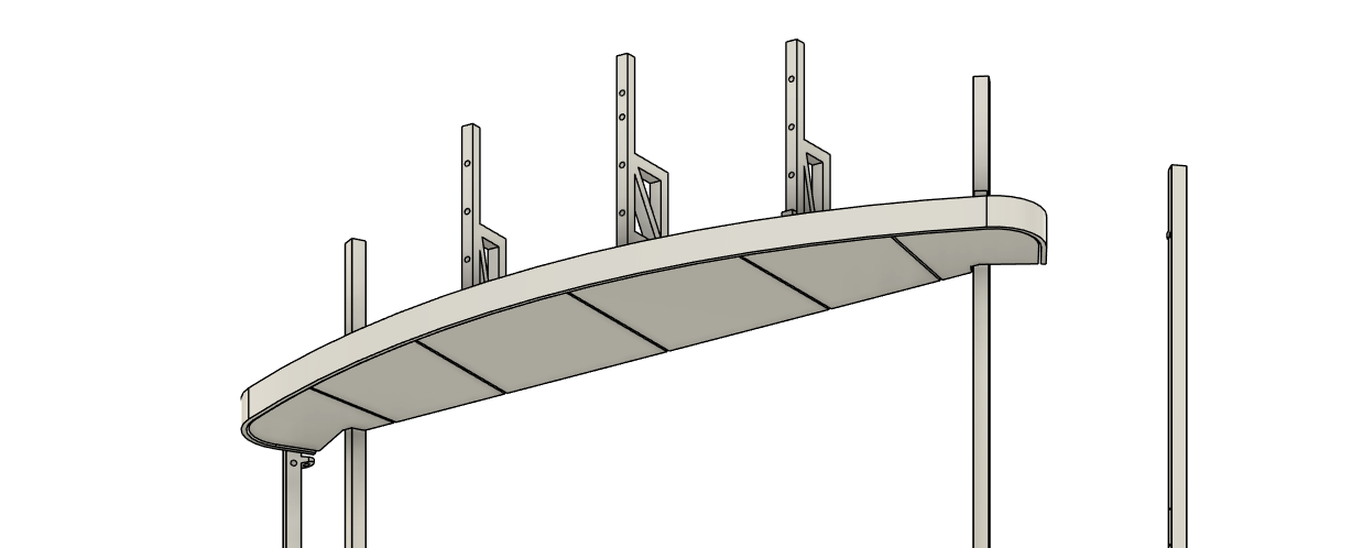
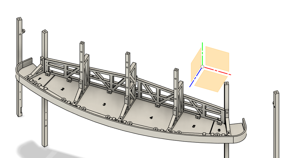
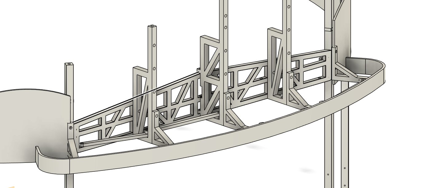
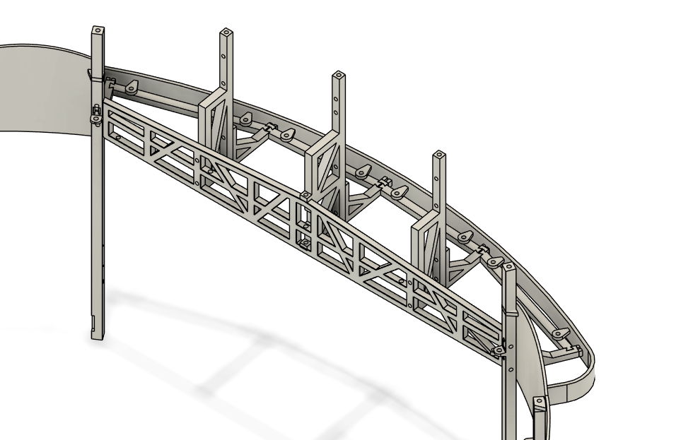
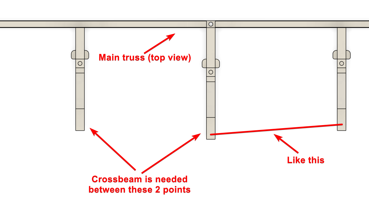
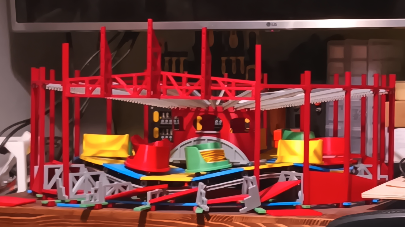
So from the main truss, there is some more parts that stick out, and they need a support beam between them to keep them at the correct distance and to hand the front canopy bezel on. The thing is, im not really sure the best way to join the beams to the sticky out truss part.
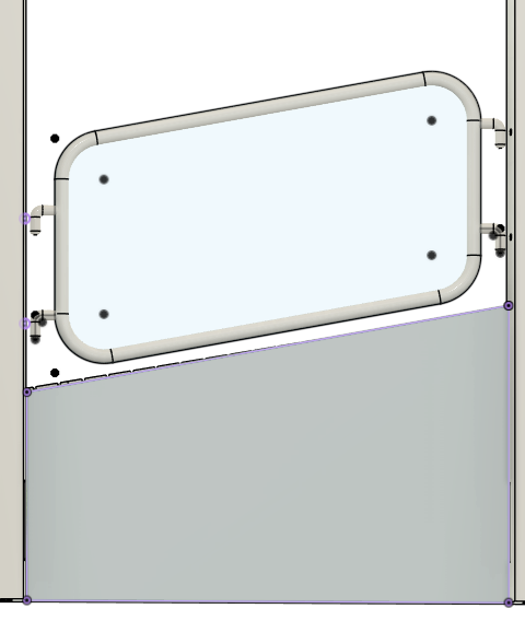
This probably explains it better

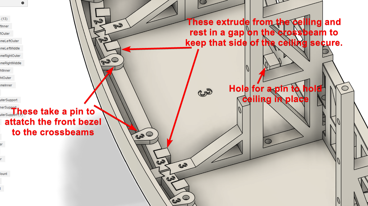
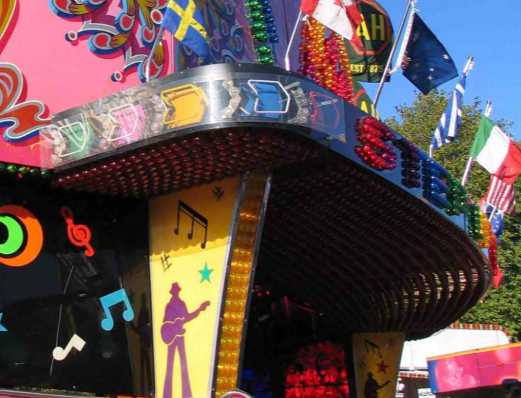
I dont want to increase the thickness of the truss, as it will look odd, and these parts will be visible in the final model (as they are on the original ride).
Originally i was considering using a single pin, with staggered crossbeams, that way the pin would secure 2 crossbeams. But it look really weird, and i wasnt happy with it.
Then i considered using slots, which the original ride uses, but because these are 3d printed, the slots would need to be fairly chunky, where as the ride uses metal, so it can be fairly thin. But i have some crossbeams that go between the sleepers on the ride, and they use slots, but are kinda crap, always popping out of place and such. But that could be simply because i didnt make the slots deep enough.
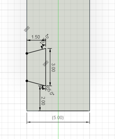
Now, im thinking about dovetail joints, but the width of the truss that holds the cross beams is only 5mm, so the dove tail would have to be 1.5mm thick on each side, with only 2mm of material between the 2 dovetails.
It would have 2 of the dovetails above, but... 1.5mm is VERY small...
So overall..
I think the pin and overlapping beams would be easiest and probably strongest, but is ugly.
The slots i have no confidence in them staying in place.
The dovetails i have no confidence in the ability to actually print them at such a small size.