Over the last couple of days ive been working on the handrails for the waltzer.
When i first started the waltzer i did actually make some of the old wooden handrails (but 3d printed obviously), i printed one out to test and it looks nice. But the modern waltzers are usually upgraded to metal handrails, presumably for safety and being less fragile 🤷♂️
These are the old handrails

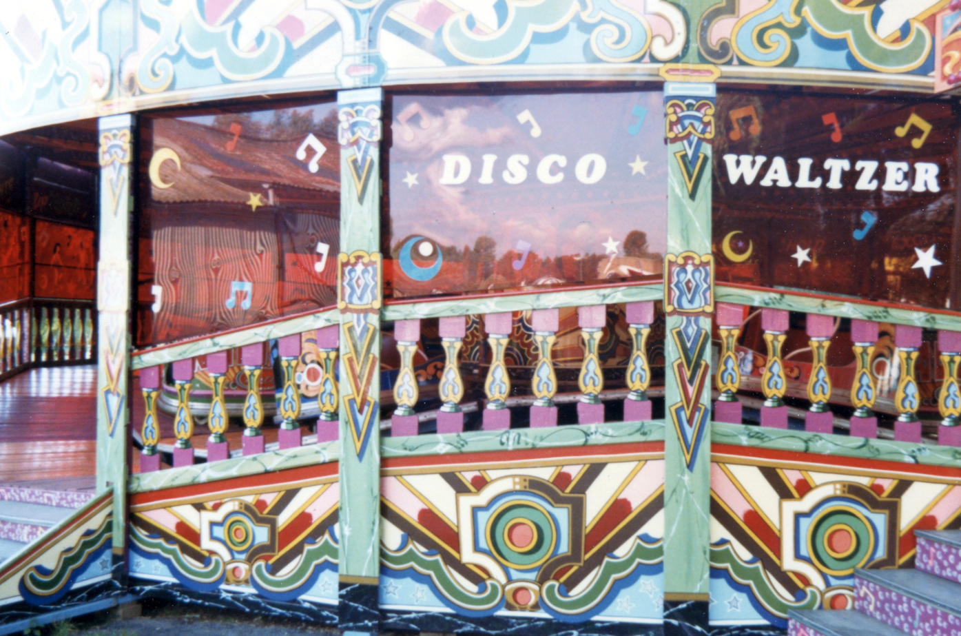
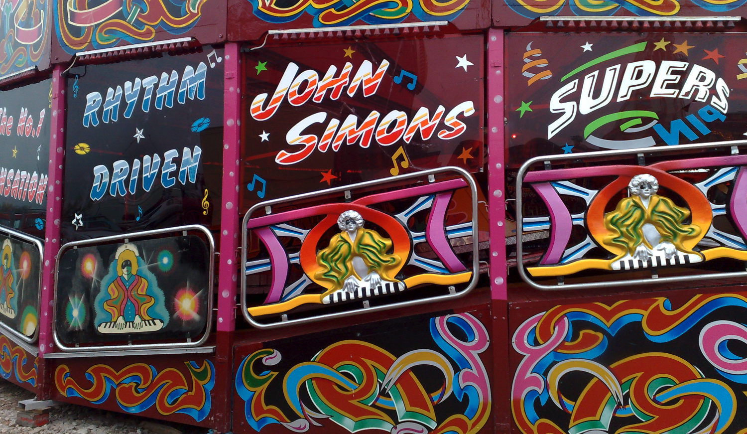
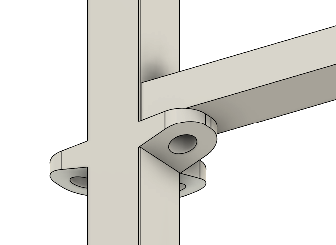
These are they "new" handrails most waltzers use.
Anyway, the biggest hurdle i have come across when working on these newer handrails is the fact they are metal. I had some 1.5mm metal rods left over from hinge joints on the moving platforms, So i thought i would bend them into the shape i need, I even brought a little jig thing that is designed for it, but its WAY harder than i originally imagined.
The spring back from the metal is pretty substantial, and although the handrails are a fairly basic shape, it was really difficult. I would also need to use the same method for the safety bars in the waltzer cars, and those bars have some pretty tight turns, so i dread to think how hard that would be to do accurately.
I looked around for some "metal" 3D printing filament, but what was out there was expensive, and it wasn't particularly metal looking to be honest. Then i watched a video by Peter Brown, he did a few "stained glass window" projects that used electroplating to cover some lasercut plywood with copper, But that was way overkill for what i need it for.
I had a look around and found people talking about using chrome paint or markers, which i wasnt aware was a thing, So found a Molotow Chrome Marker on amazon.
Honestly i wasn't expecting much, but holy cow, the results i got look incredible.
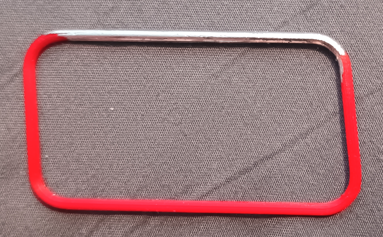
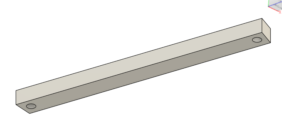
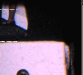
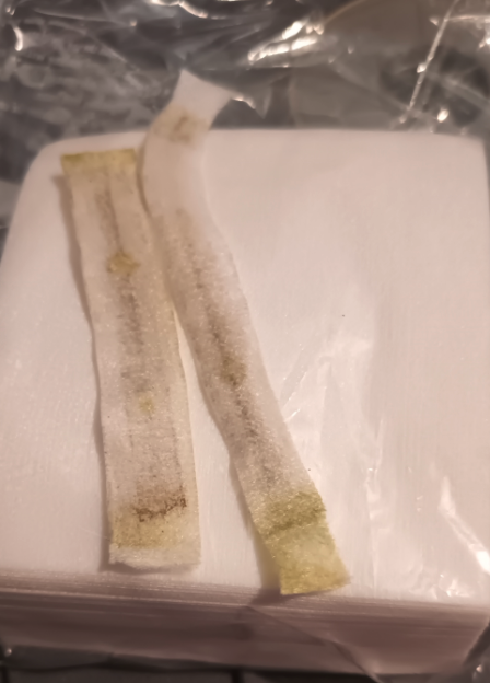
The picture below was a test print of a partial "metal" handrail i made the other day, i used the marker on it...
Tell me that dont look good...
Ive looked around and im not sure how durable it is, nor how long it takes to dry (the pen came with no instructions) but other people have used the spray cans and air brushed it and say it can take 2-3 days to fully dry.
A few people have mentioned that its pretty delicate and to use a clear coat on it, but then some other people say that clear coat will dull it and basically just make it silver colored without the shininess.
Im really impatient, so i will probably start poking it pretty soon to see how long it takes.
Its fine, its just a test piece😂