I spent a long ass time last night just capturing random shit from tapes. I found one tape that is basically just full of recordings of music performances on things like cd:uk, citv, nick, top of the pops and such, Which are kinda cool.
TV studio sets back then were way more creative. Now everything is just giant LED video walls, which make them basically all look the same. But skimming through these tapes, they had actual fucking tv sets, with actual props and things.
Oh, ive been making some bat scripts / files too, That way i haven't got to remember the 10 billion commands to do basic shit.
Why the fuck they don't just make a nice, simple UI that lets you do all the basics with a few clicks i have no idea 🤷♂️
Im Still trying to work out the linear audio issue. Im gonna get the scope out and double check that everything looks ok. I cant see anyone else having the "super deep voice but still the correct length / speed" issue.
I asked chatgpt, Which is basically saying "its the clock", "its the mode", "its the ground", basically throwing shit at a wall and seeing what sticks. So im just gonna poke around and see if i cant find anythig that looks sus on the hardware side.
I cannot work out this fucking linear audio shit. Ive tried capturing 3 different ways, all have the correct sound except the linear audio captured using vhsdecode😑
Ive been capturing some test stuff just to see how to whole workflow will go without having to do an entire tape.
Once again, the wiki is fucking crap. I know Harry (the guy who wrote most of it) words hard on it, but fuck me if its not like looking for a needle in a haystack.
Im trying to work out how the linear audio post capture workflow works.
Im using the clockgen mod lite, which outputs audio at 78125hz, and when i listen to the audio, i can hear the video, But i dont understand where the "sync the audio with the video" part comes into play. There are instructions about using the "AutoAudioAlign" tool, but they all seem to assume your using the original clockgen, which doesn't use the same sampling rate, and the output is usually significantly different than the runtime of the video.
I really have no idea what to do next other than ask in the discord, but i really dont wanna do that. I cant really put into words the issue so that it make sense, which makes it harder to explain to people that apparently know what they are talking about.
It was the panel mount usb3 adapter thing. I just plugged the hardwired cable back into the pcie adapter and it works fine.
Im testing the setup for the vhs player but its hanging when i boot, so that adapter is either a dud (likely) or the pcie signalling cant handle more that the extra cable length.
Im guessing the adapter is just crap, purely because the port on it looks cheap.
Oh well, was worth a try. Back to it being hardwired together🤷♂️
I have no idea where im gonna put this vhs player / pc monstrosity i have. I dont have room in my usual place. I think im gonna have to put it on the shelf above my bed, but then im gonna have to have a power cable dangling from the shelf 😭
Urgh, i need to update the site to handle more than 9 pages 😭
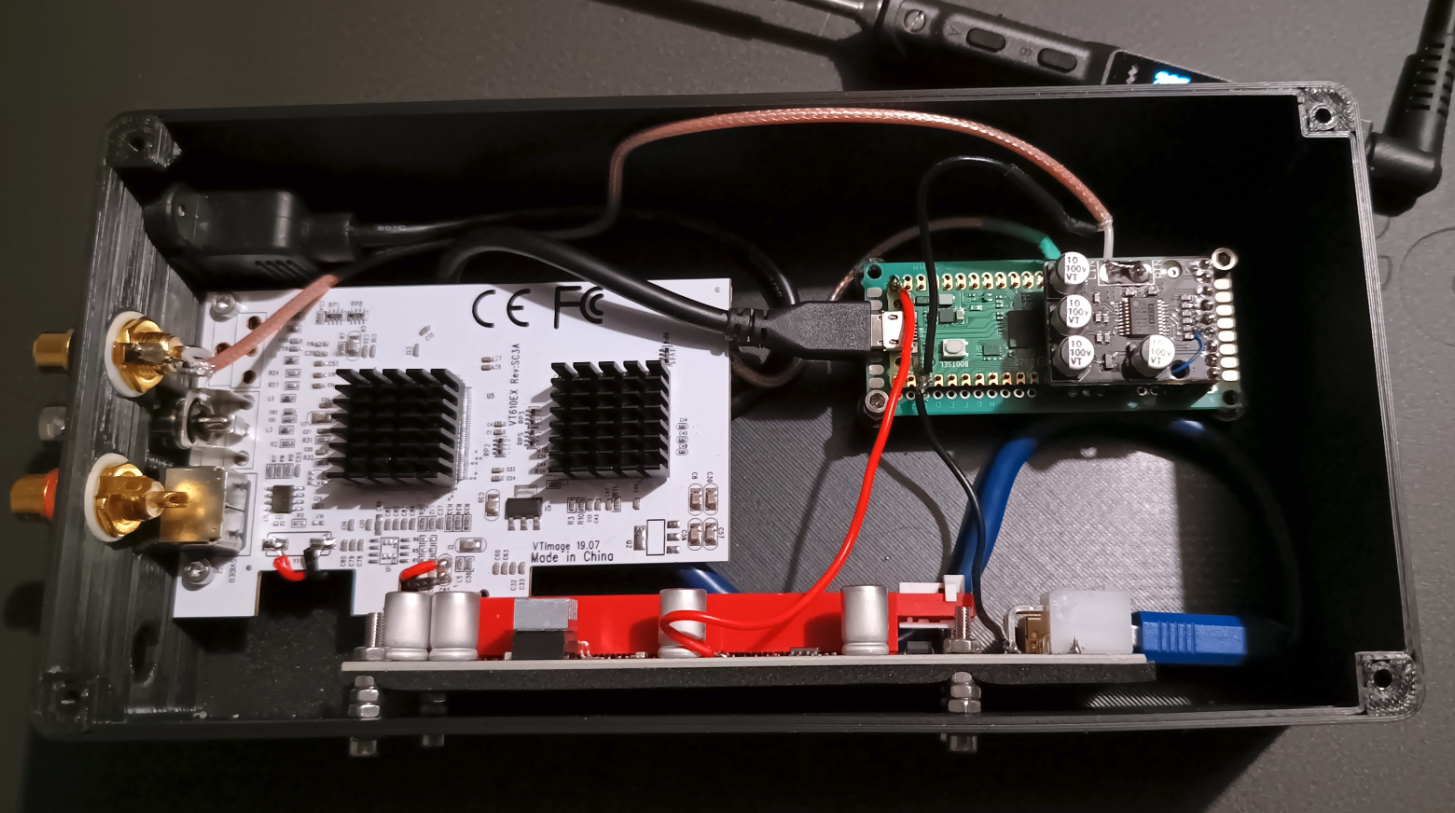
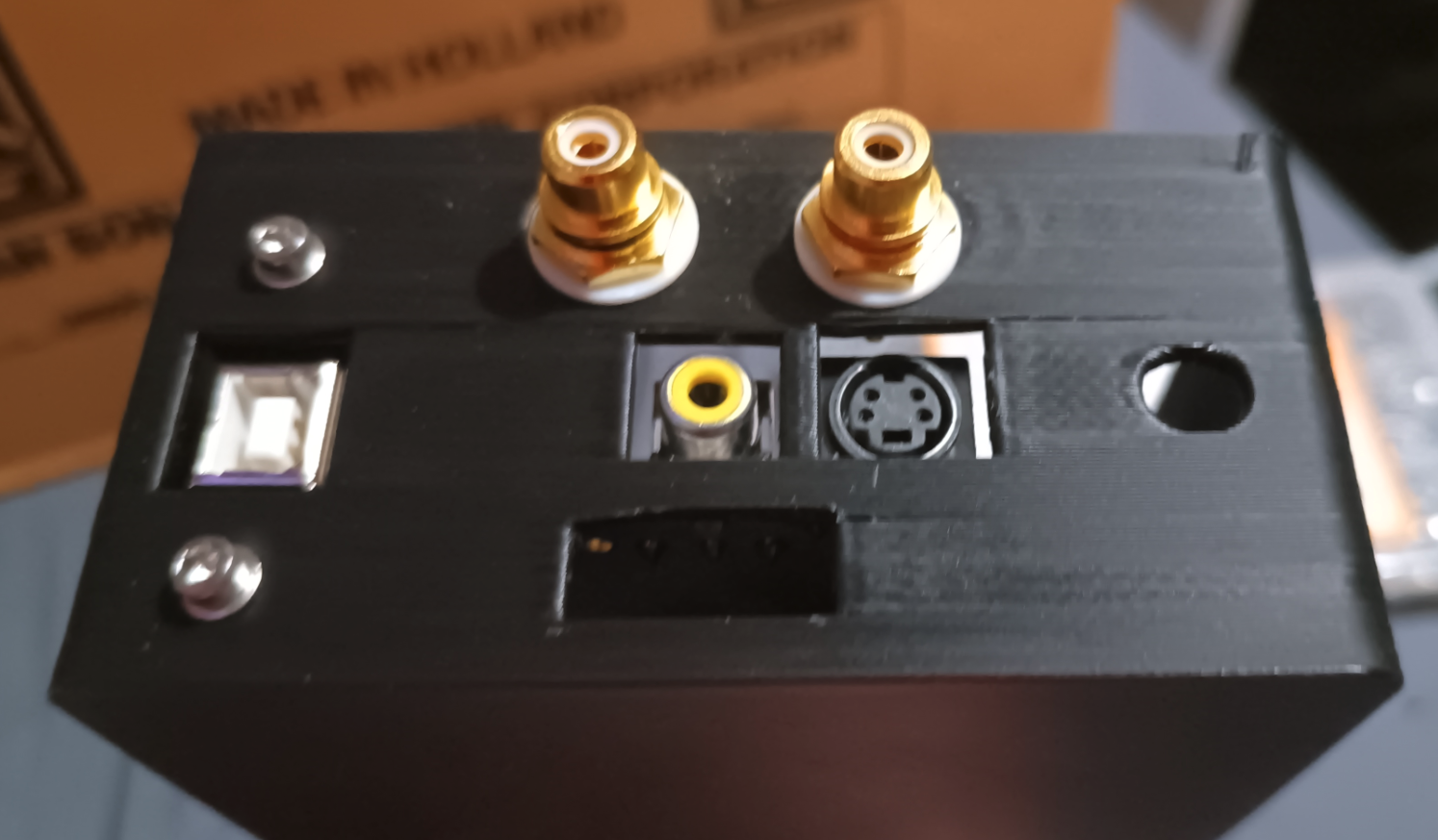
The little box thing i have everything in is pretty much finished. Unless the audio doesnt work then its not finished lol.
Here are some pics.

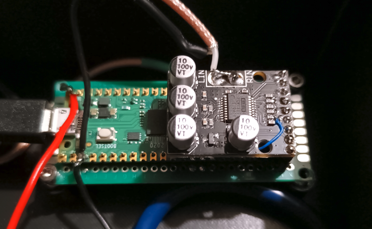
Seems as its mono audio, i joined the left and right channel inputs, Im sure there is a reason that shouldnt be done, but i cant think of one, so im trying it. All it means is i wont have to duplicate the audio channels manually. In theory.
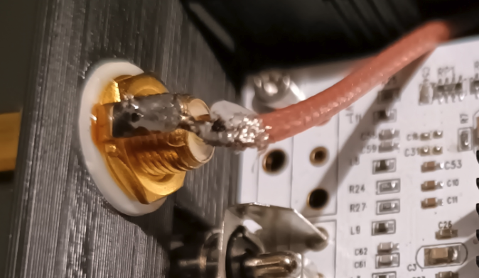
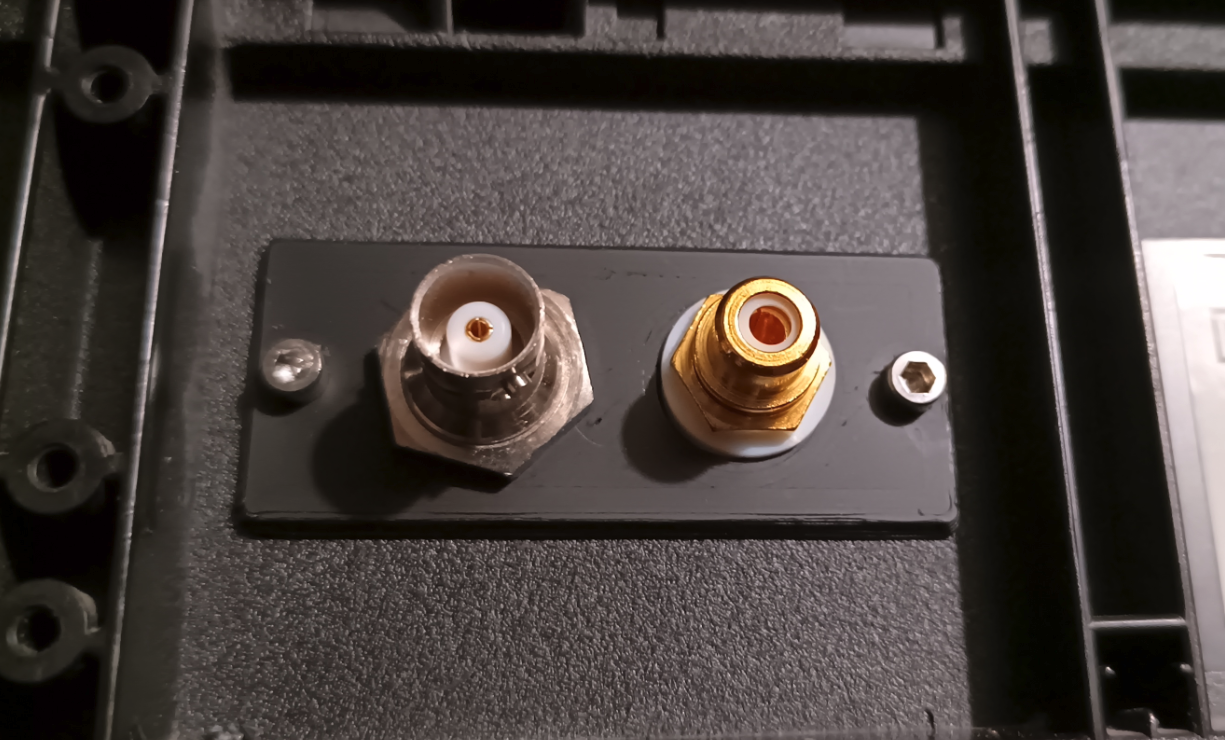
Audio input rca jack. The soldering is shit, but its solid and tests good continuity wise.
I had some cable left over from the bnc cables, so i used that.
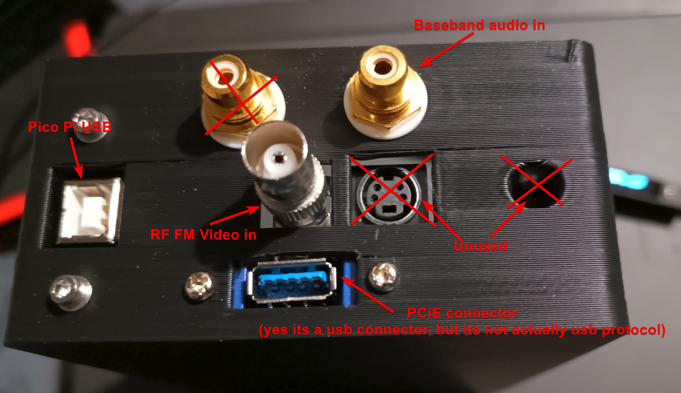
The usb port on that blue adapter looks cheap as fuck. I hope it works as expected😐
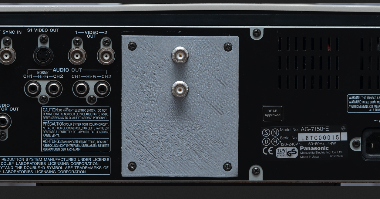
I was just soldering the audio connectors up, and realized i needed another mount hole, so i adjusted the mount plate i made for the single bnc connector.
Also, i put 2 audio jacks on the case thing i made, but baseband audio is mono, ive checked the schematics for the player i have, pins 1 and 3 on the scart connector are joined, with those two being the left and right audio channels. So there doesnt seem much reason to use 2 cables.
Unless im missing something? 🤷♂️
It took WAY to long to find the correct command to actually capture the video. Im still not actually sure its the best command, but its one that worked.
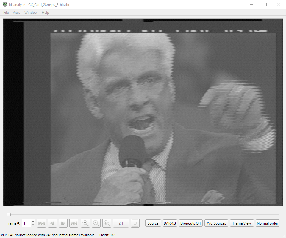
This is the output from my first test capture, it was just a 10 second capture to test the setup. I havent tested audio yet, i still need to hook up the cables and what not. But im waiting for amazon to deliver me a usb 3 panel mount, so the little box isnt always hardwired to the pc.
This is the "source" output, you can see the VBI at the top, presumably for subtitles.
This is the Chroma / Luma output.
I dont really know what im looking for in terms of defects, but ive seen some that have rainbow and crosshatch patterns faintly across the video, but i cant really see any of that on my capture? Unless ive gone blind.
Im trying to pluck up the courage to ask in the discord for there opinions😭
It must have been the usb cable, I checked the 5v and its looking pretty solid, and the 3.3v output from the pcie adapter is looking good too🎉🎉
The original usb cable i was using for the pico pi was a beefy fucker too, But having that much voltage drop along a meter long cable is terrible.
Just goes to show, dont judge a book by its cover. Even if its a nice thick shielded cover 😭
Lets hope it holds up through hours of capturing🤞
Well, it seems like the computer is recognizes the devices, which is good.
=== CX23880 Video Capture ===
03:00.0 Multimedia video controller: Conexant Systems, Inc. CX23880/1/2/3 PCI Video and Audio Decoder (rev 05)
/dev/video0
=== CXADC Audio Device ===
Bus 003 Device 002: ID 1209:0001 Generic pid.codes Test PID
Subdevice #0: subdevice #0
card 1: CXADCADCClockGe [CXADC+ADC-ClockGen], device 0: USB Audio [USB Audio]
Subdevices: 1/1
Not sure why its recognizing the cx card as a 23880, its a 25800. But thats probably just a linux driver thing. I haven't actually changed anything on the system yet, this is just a bare linux mint install.
Im gonna test the 5v rail and see how thats holding up. It dropped to 4.3v the other day when testing the pcie adapter mod i did. Ive changed the usb cable, so hopefully that has fixed it.
I have been working on the vhs thing today. Just setting the pc side up, and second guessing all my choices 😭
This happens with all my projects, i get to the point i have to test something, and i just cant do it. Its not like im afraid of failure, i know there is a 99% chance its not going to work, i think its just the dread of actually having to change things up and troubleshoot what the issue is when it is confirmed to fail.
I hate troubleshooting.
All i have to do now, is plug the pcie adapter cable into the adapter, and connect the pico pi to the pc, and then i can start testing. But altho the physically doing it part is easy, its everything that can come after that.
I probably sound like a right mental💀
Just spotted this on the vhsdecode wiki
And i thought my first layer was bad 😂
Oh, i forgot to add the pictures of the case lol.
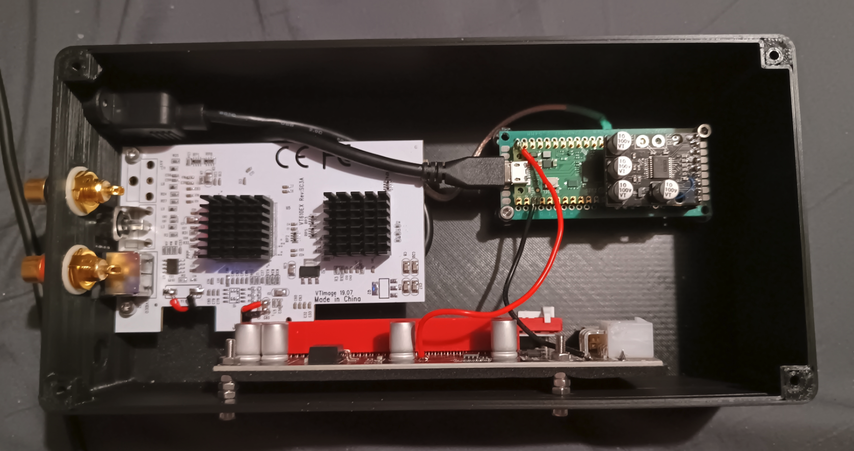
Im not exactly happy with it. But it does the job, and its a waste to reprint it when i only need one of them. If i was gonna print another, i would modify the hole under the svideo connector, its for the usb cable, i would like to add a panel mount like the one on the left for the pico pi. I would increase the height of the standoffs on the pico pi board, and i would add standoffs for the pcie adapter board.
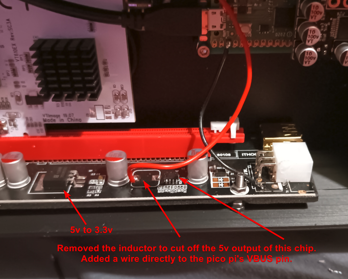
I have done something a little hacky / janky. I have removed the 12v pcie power.
I looked though the datasheet for both the chips on the cx card to see if they use the 12v rail on the pcie connector, i also checked the 12v pins to see if they go anywhere else on the card, but i couldn't see anything. So hopefully i dont need the 12v input jack (the hole on the right side of the end of the case), as i can just use the pico pi's 5v, and the 5v to 3.3v regulator on the pcie adapter board. Ive tested it, and it seems to be working fine. Except the pico pis vbus rail is dropping to like 4.4 volts, which im not happy with.
If it causes any problems, i can just add the inductor back and add the 12v power jack. It would suck needing a second power supply, but not much of a choice.
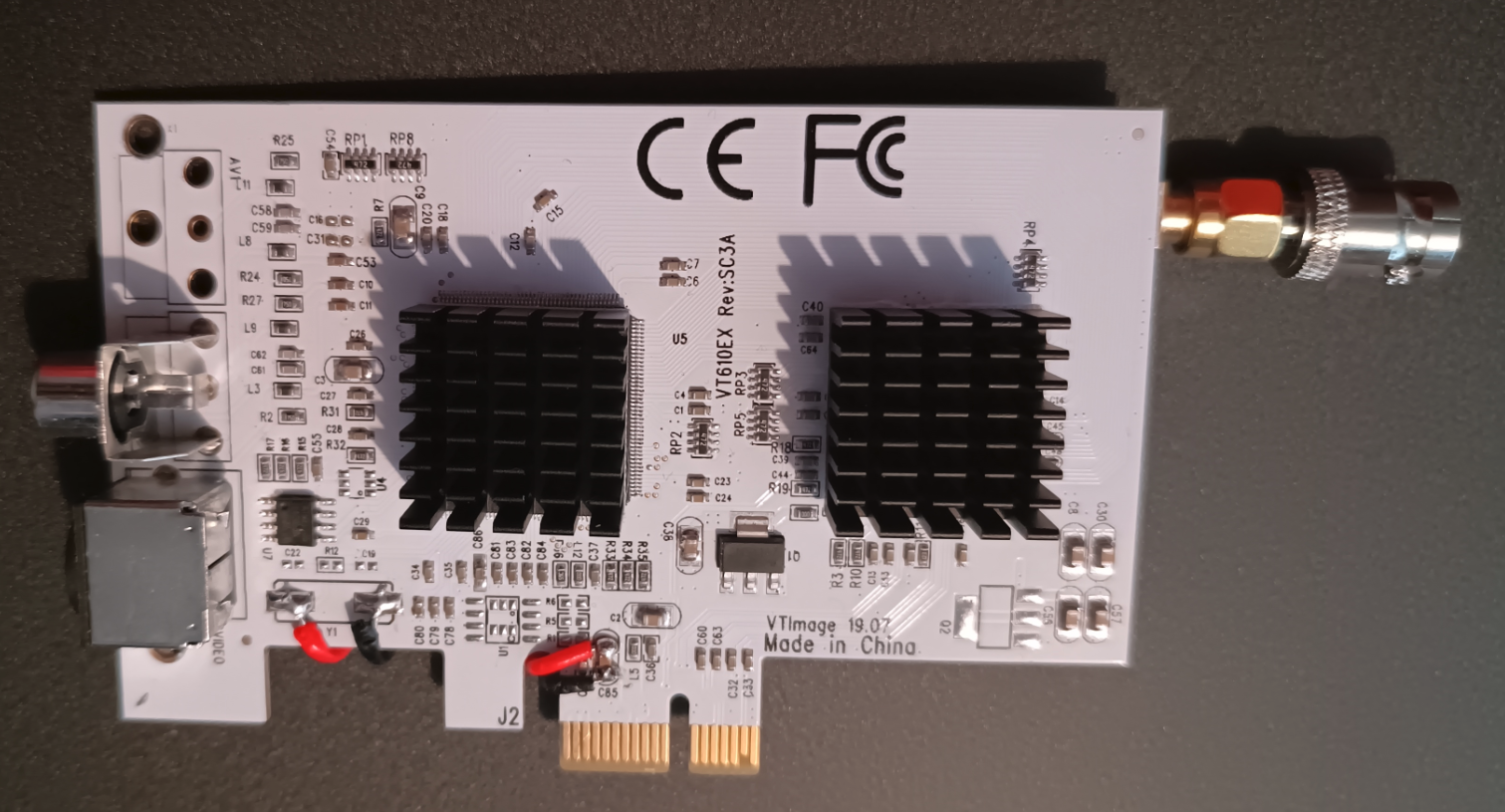
Heres what ive been constructing. I havent actually tested it yet, so it may well be wrong.
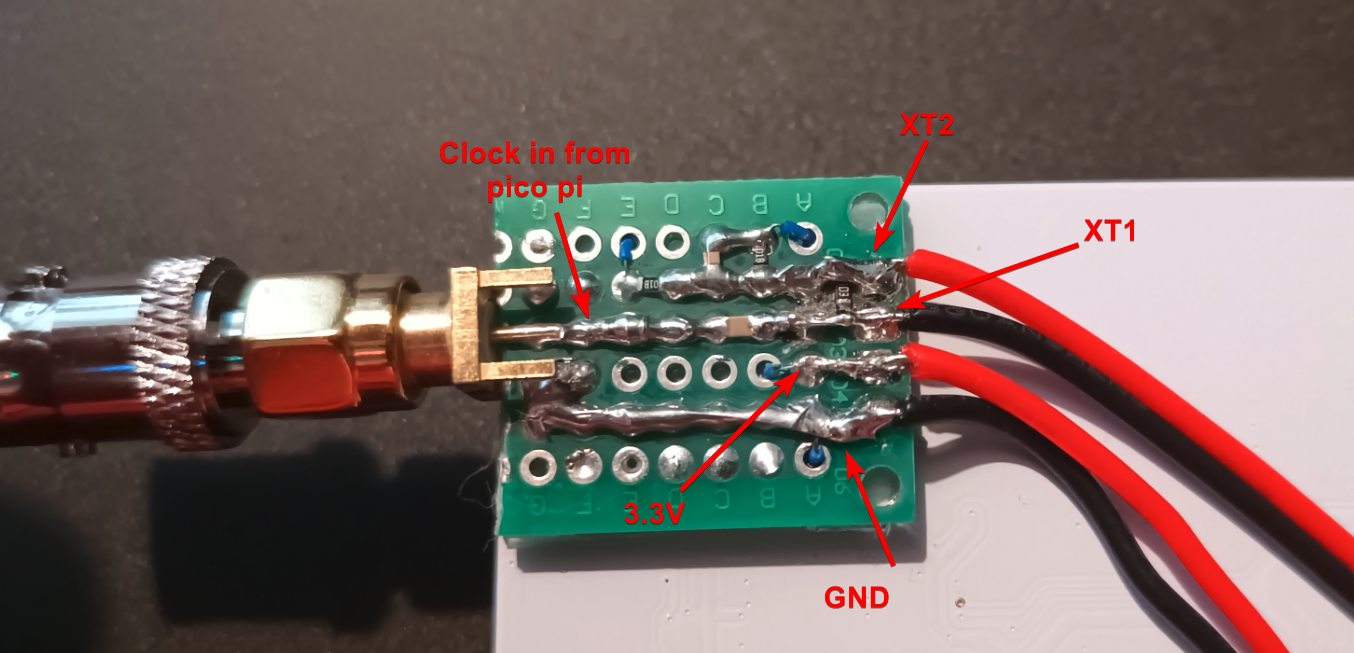
The "CX Card". The red and black on the far left is for the clock, the ones on the right are for power and ground.
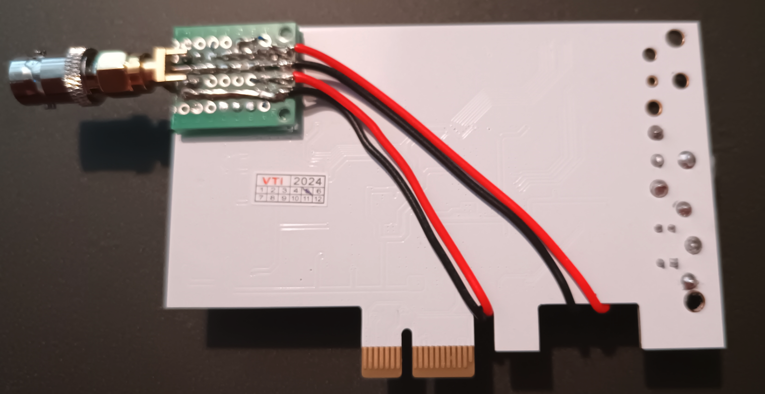
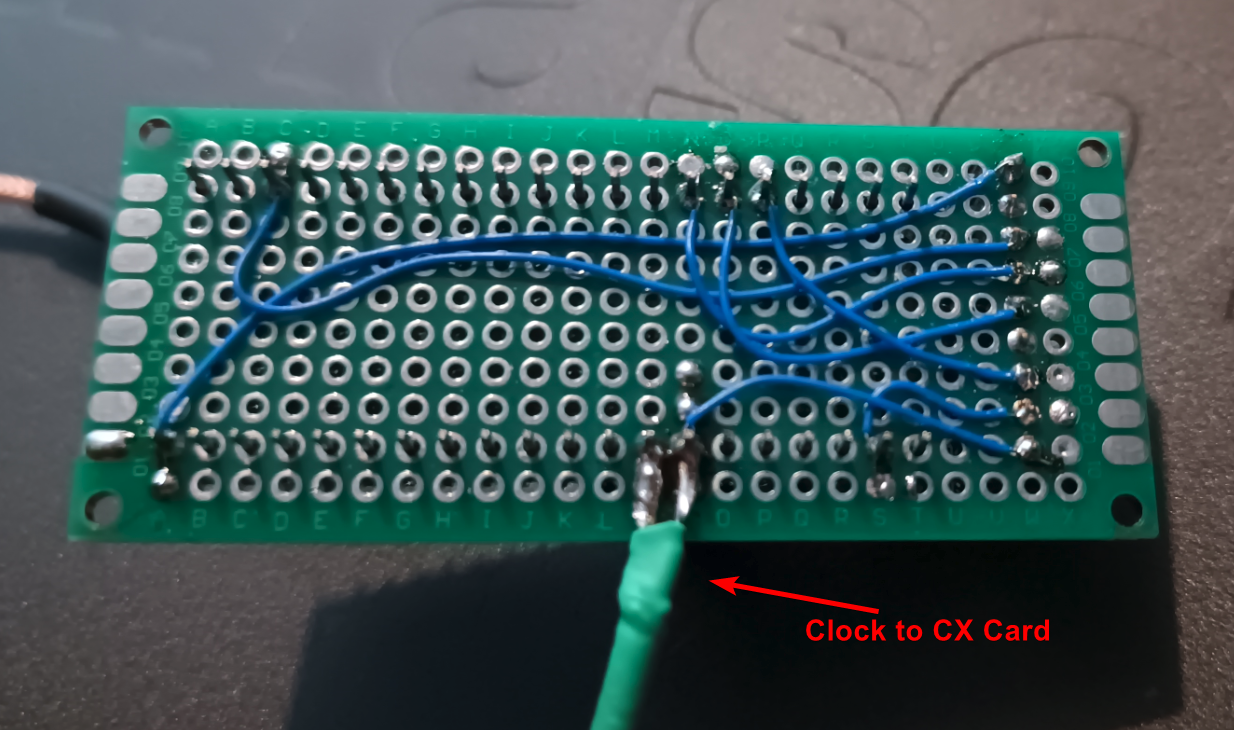
This is a fucking aweful picture, i havent worked out why my phone has such weird focus issues. Anyway, this is the back of the CX card, with the little clock board thing. They sell / give access to a real pcb, but im not ordering them and waiting for 2 weeks, so i used some double sided perf board and made my own. No idea how good it is, but its all wired according to the schematic.
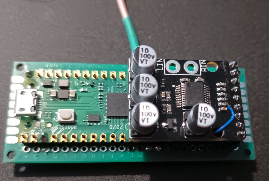
The clockgen lite mod. Yes i know most of the pi gpio pins arnt soldered, I didnt see the pint if they are unused.
Found it, it was with my filament... for some reason🤷♂️
I need to work out where my new "safe place" is when i put things there. Cause ive lost something, i know i moved it when i was looking for that pcb the other day, now i cant remember where i put it 😭😭